Showing posts with label project. Show all posts

Thursday, 28 July 2016

Design Of Police Siren Using NE555


CLASS WORK PROJECT 

DESIGN OF POLICE SIREN USING NE555 
 
Introduction
A siren is a loud noise making device.
Sirens are mounted in fixed locations and used to warn of natural disasters or attacks.

Sirens are used on emergency service vehicles such as ambulances, police cars and fire tracks

Background
This police siren simulated electronic project uses two 555timers IC to generate a sound similar to a police siren.

A single 556 timer IC which consists of two 555 timers can also be used. In this circuit both of the timers are configured as a stable circuit.

Problem Statement
Due to the need to alert people in case of emergencies such as police vehicles and ambulances.

Significance of the project
The whole idea of the siren was to alert the public about emergency cases. The Siren finds application in police vehicles, ambulances.

General Objective
The general objective of this project was to understand the operation of a siren. By making a run up of the project, theoretical knowledge was transferred into practice and during the hardware implementation, practical skills such as a printed board implementation, circuit testing and soldering were enhanced.

Specific Objective
To design a simple Police siren.

Scope of the study
The project only focuses on producing loud sound which brings about sound pollution to the environment. Some instruments such as bazar where hard to find and  generally expensive.

It took us a lot of time to make a working siren without mistake.

Circuit diagram:


Materials and Quantity 

Capacitors  
100µF    1          
100nF    1   
1µF        1   
10µF      1 

Resistors  
68KΩ     2 
8.2KΩ    2  
1KΩ       1  

Diode  
1BH62    1  

IC    NE555    2  

Buzzer  
64 ohm, 500mW    1  

Battery  
10v    1  

LED  
Red &blue    2

Variable resistor        1  

Print board        1

Jumpers
   
Switch        1    


TUMUSIIME BENON      
SEKITTI HAMIS     
ARYAMANYA EDWIN       
SEGUYA ENOCK      
SISYE GARVIN      
KASAMBA GEORGE     
ANGURIA MAX     
MUTABAZI  ARBAN     
KIBALAMA JOEL    
SITAKU OSCAR     
UMA STEPHEN      
ARIHO LEWIS   
Share:

Series and Parallel Connection Of Bulbs and Socket Outlets

CLASS WORK PROJECT
 
CONNECTION SERIES AND PARALLEL OF BULBS AND SOCKET OUTLETS
 
Introduction
The project is showing 2-lamps in parallel controlled switch, by 2-way switches with intermediate switch, 1-gang, 1-way switch controlling two series connected lamps, single and double socket outlets connected in parallel and single and double socket outlets connected in series.

The project was to test the lighting of bulbs connected in series and the parallel and voltage of socket outlets connected in parallel and in series .

Objectives
  •  To compare the advantages and disadvantages of series over parallel circuit.
  • To demonstrate the operation of two way switches with intermediate switch
  • To equip students with the knowledge of wiring two different wiring system i.e. series and parallel
Challenges
  • There was a problem of lack of enough money to buy all the components
  • Difficulties in designing the circuit diagram since only a list of materials was given
Tools used 
  • Pliers: This was used to hold cables as well as peeling off insulators on cables
  • Hammer: This was used to fix nails into the board  
  • Tester: This was used to test the presence of current in a circuit 
  • Screw driver(flat and star): This was used to loosen and tighten knots
Materials used
  • Bulbs
  • Lamp holders 
  • Junction boxes 
  • Socket outlets 
  • Switches Cables 
  • Clips and nails 
  • Intermediate switch 
  • Power cable
Safety precautions
  •  One should always observe insulation of tools to avoid electric shock
  • Power must be switched off whenever an equipment is being assembled 
  • Do not work alone while working with high voltage electric equipments
  • Chairs and stools should be under the benches when not in use 
  • Wearing a ring or watch can be hazardous in an electric lab since such items make good electrodes for the human body
  • Never touch electrical equipment while standing on a damp or metal floor
Procedure
The main switch was placed in its position and the power cable connected to it
 
The testing of current was done by use of a tester and then plugged out of the power supply
 
Junction boxes were fixed in their rightful position with two on either sides of the main switch and the cables of 1.5mm and 2.5mm were connected to the switches, lamp holders and socket outlets respectively from and in the junction boxes
 
To the right, a single socket outlet and a double outlet were connected to one junction box in parallel and another single socket outlet and double socket outlet were connected to the second junction box in series
 
To the left, one junction box was connected to lamp holders in series with 1gang switch and their circuit closed. Another junction box was connected to lamp holders in parallel and two 2-way switches with an intermediate switch in between them
 
Conclusion 
All the bulbs light but with two bulbs in series blinking
When the intermediate switch is turned off, the 2-way switches do not function or do any task and the bulbs in parallel do not light
The 1gang switch controls both bulbs in series since current flows along only in one path


ALIGANYIRWA YOSIA                          
NUWAMANYA ANANIA                         
MUGABE WILSON ROBERT                 
WESENE AMEDI                                    
MUTESI BRENDA                                    
NAMBUYA RECHEAL                            
ASIIMWE ROBERT                                 
TURYAHABWE FRANK                            
MUSHABE AUGUSTUS                           
BWAMBALE JOSEPH                              
KAMUMBERE PAUL                             
Share:

Design Of Dual Power Supply System 5V and 12V Output

CLASS WORK PROJECT DESIGN

DESIGN OF DUAL POWER SUPPLY SYSTEM 5V AND 12V OUTPUT


Introduction

In this chapter we would be discussing the design and implementation of the dual power supply system. Electronic circuits using tubes or transistors required a source of dc. power. For example, in tube amplifiers, d.c. voltage was needed for plate, screen grid and control grid.  Similarly, the emitter and collector bias in a transistor had also to be direct current.  Batteries were rarely used for this purpose as they were costly and required frequent replacement.  In practice, d.c. power for electronic circuits was mostly conveniently obtained from commercial a.c. lines by using rectifier-filter system, called a d.c. power supply. 

The rectifier-filter combination constituted an ordinary d.c. power supply.  The d.c. voltage from an ordinary power supply remained constant so long as a.c. mains voltage or load was unaltered.  However, in many electronic applications, it was desired that d.c. voltage should remain constant irrespective of changes in a.c. mains or load.  Under such situations, voltage regulating devices were used with ordinary power supply.  This constituted regulated d.c. power supply and kept the d.c. voltage at fairly constant value.  
Background
A transformer was used to step down the AC line voltage to a smaller peak voltage Vm, which had to be somewhat larger than the ultimately desired DC output.  A diode circuit rectified the AC signal and a capacitive filter bank was then used to “smooth” or “filter” the rectified sinusoid, producing a waveform with predominant DC component.  Under normal loading conditions there was always some residual periodic variation or “ripple” in the filtered signal.  If the application required very low ripple and constant DC output over a wide range of loading conditions, then an active regulation was required to further reduce or eliminate this residual ripple.  Most active regulator circuits would require a certain minimum input-output voltage differential for proper operation.

Problem statement
To buy two different chargers become expensive to low class living individuals, therefore the team decided to designed a charger that can charge two different d.c components at the same time so such the expenses of buying two chargers is reduce by a quarter or even a half.  

Significance of the project. 
  • The design was not so complex i.e. it required few components.
  • It required less space unless heat sink was used. 
  • Did not generate noise and heat. 
  • Fast transient response meaning that the rate at which the capacitor discharged was fast. 
  • Low cost.
General Objectives  
The general objective of a rectifying circuit was to convert a.c power to d.c power.

Specific Objective  
 To generate a dual power circuit that could supply two different d.c devices that used 5V and 12V at the same time.

Scope of study
To design a dual power supply of 5V and 12V dc with the following specification of both input and output. 
  • A.C input of 230V
  • A.C output of 14V 
  • D.C input of 14V 
  • D.C output of 5V and 12V.

Methodology 

Tools used. 
  • Soldering lead.
  • Power source. 
  • Soldering gun.

Materials used  
  • Step down transformer
  • Diodes 
  • Capacitors. 
  • Voltage regulators 
  • Resistor 
  • LED 
  • Printed board 
  • USB head 
  • Bread board 
  • Jumpers

Bill of quantity 
S/N    Components                            Specification        Qty
1        Step-down transformer          230V/14V, 1A         1   
2        Diodes                                    1N4004                  4  
3        Capacitors                             1000µF                   2   
4        Voltage regulator                   VR7812                  1    
5        Voltage regulator                   VR7805                  1   
6        Resistor                                  1kΩ                        1   
7        LED                                        Red-5V                   1   
8        USB head                               5V                          1  
9        Printed board                         Ea                          1   
10      Jumper                                    Ea                         15   
11      Soldering lead                        Role                      1   

Circuit diagram


Safety precautions. 
  • Avoid touching capacitor before it is completely discharged.
  • The terminals of each components were appropriately marked for correct connection to avoid short circuit. 
  • Avoid connecting components when power is on. 
  • Avoid touching soldering gun when it is connected to the power source.
Procedures
  •  The four diodes were connected as shown to form the rectifying circuit with its input connected to the secondary winding of the transformer while its output connected to the input of power regulators coded VR17812 and VR27805.
  • Each of the input terminals of the two regulators were connected to the ground through capacitor rated 1000µF. 
  • The reference terminal of each of the regulator was connected directly to the ground. 
  • Connectors were connected to the output and ground of VR17812 to generate 12V d.c output. 
  • 1KΩ resistor in series with the LED were connected across the output and ground of VR27805 and connectors were connected to both the output and ground terminal to generate 5V d.c output.
Mode of operation
The above circuit obtains power from a 230V AC mains supply voltage and fed into a step down transformer for transforming higher voltage supply to lower one. The transformer TR1 is of 230V primary, 14V secondary and 1A step down transformer. The stepped down voltage is fed into the bridge rectifier made of four 1N4004 diodes for the conversion of AC supply to DC one. 
The output from the bridge rectifier was filtered by the capacitor C1 and C2 to offer a steady DC level to the input pins of the regulators used in the above circuit. The DC voltage is then fed in to the IC 7805 which is a 5V regulator and also to the IC 7812 which was a 12V regulator. The output obtained from the 7805 & 7012 are 5V and 12V respectively. A LED D5 was connected through the current limiting resistor of 1KΩ to indicate the state of the device.
Schematic 


Conclusion
After the components were mounted on the printed board and the circuit was powered through at a step down transformer, the required voltages of 5V and 12V dc were obtained across the terminals.  

Challenges
In the process of designing and construction of the dual power supply, the following problem were encountered, 
  • Most of materials used in the construction of the dual power supply were expensive.
  • There was no enough time given to the students for studying and designing of project which caused a lot of expenses. 
  • The project was new to the students since it was the first electronic project that they have ever studied and we had the problem of determining the terminals of the electronic components we used. 
  • The circuit did not have the protective equipment’s which put all the component under used in great danger. 
  • Another problem was that the circuit produced heat and this can burn the circuit components.
Improvement to above challenges
In order to have an efficient dual power supply, the following components has to be incorporated in the circuit to solve the problems notices during the design and operation of the system. 
  • A.C Relay – this relay has to be connected before the rectifier circuit to monitor voltage, current, frequency, surge variation and lose connection.
  • D.C Relay – It has to be connected at the output to monitor output parameters. 
  • Heat sink – should be connected with the regulating circuit to dissipate heat generated by regulators.
                                                   
KIMULI ISMAIL   
LWANGA RICHARD   
ATENY GABRIEL AGUTO   
KASIIMBURA OSBERT   
SSEMWOGERERE DANIEL      
FATUMAH SULAIMAN    
KITYO MARK ANTHONY      
BUKENYA IVAN    
BOGERE INNOCENT       
DDEMBE JOSIAH   

Share:

Tuesday, 5 July 2016

Design Of Automatic Night Light Detector

DESIGN OF AUTOMATIC NIGHT LIGHT DETECTOR

( Case study: Kampala International University)

SEMESTER RESEARCH  PROJECT 

BY

  • NABASA HIRIJI                
  • LUNKUSE STELLA      
  • OGWAL EMMANUEL              
  • LUCY HAKIM                      
  • SSEMAGANDA RICHARD      
  • RWOTOLARA DANIEL      
  • SIMON JUMA BULLEN     


LECTURER’S NAME: MR. ADABARA IBRAHIM

©2016 all rights reserved

ABSTRACT

The lighting systems in place nowadays mainly rely on the presence of users who have to switch them on or off manually. Due to this manual operation the lighting systems are expensive where there have to be switches in place, energy consumption is also high especially when the lights are left on during the day time hours when they are not necessary and the switches are prone to wear and tear.

This research project solved the manual operation problems and able to reduce the cost since it is automatic and it switches on and off depending on the time of date.

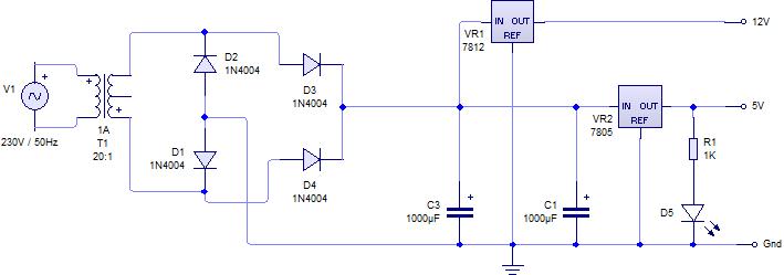
First designed a 5V regulated power supply using a transformer, bridge rectifier, capacitor and a voltage regulated.

Design the switch that will be on during night hours and off during day hours. The implementation of the circuit was done by use of bread boards, soldering gun and lead.

Testing of the research project was done in two distinct levels. Firstly we tested the functionality of the switch and lastly the overall system.

This research project is much economical compared to the one that is currently been used.

CHAPTER ONE 

INTRODUCTION 

1.0   Introduction
The project title is an “Automatic Night Light Detector” which uses Light Dependent Resistor, it consists of a circuit which turns on the bulb interfaced to it during night hours and it turns off the bulb automatically during day hours.

1.1   Background
The light-darkness detector is a current system that was developed in the late 1990’s. Its introduction has attracted a number of users including institutions, homesteads, hospitals and city authorities all over the world. 

1.2   Statement of problem
Energy consumption is increasing changing over time, which ultimately changes the level of global warning. Every day we work hard to reduce the level of energy consumption. This cannot be realized if our lighting systems are consuming a lot of energy.
Technology is also changing where the manual operations are replaced by automatic operations. The automatic is preferred because there is no need of constant monitoring; this helps to reduce the level of energy consumption.

1.3   General objective of the problem
The main objective of this project was to come up with a lighting system that turns on/off light automatically during the night and day hours respectively hence saving energy and it’s cost effective.

1.4   Specific objectives
The project’s specific objectives are;
To design and come up with cost effective lighting system.
To design the switching system that will automatically turn on/off lights during night and day hours respectively.

1.5   Significance of the study
The project is cost effective in terms of power consumption and installation.
The project provides reliability light intensity at all the necessary times.

1.6   Scope of the project
Lighting is very important in all institutions especially learning institutions. Without the proper light intensity learning can be a problem to students and their lecturers. Kampala International University is our case study which is one of the institutions that need the proper intensity for learning purposes. To maintain the light intensity that is adequate for this purpose we designed an automatic night light detector and with this the institution will minimize on energy consumption since the system switches lights on during night hours and switches them off during the day hence saving energy.

Circuit diagram


Soldering on PCB


Share:

Search This Blog

ITIE FACEBOOK PAGE

Engineering Practical Forum

ITIE. Powered by Blogger.